")
Filter and Separators
Filter
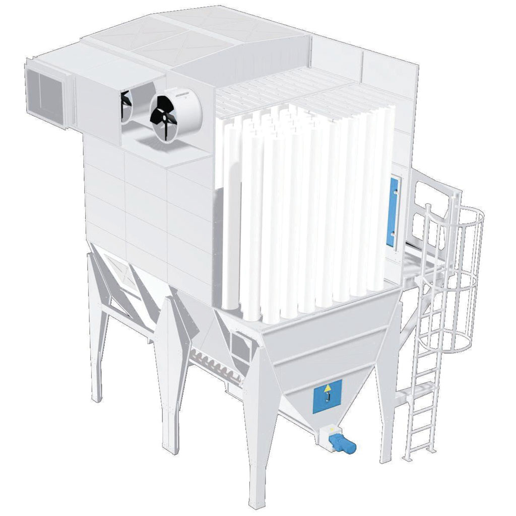
ProTechCon has an extensive range of bag and cartridge filters, ranging from extraction from a single machine using a portable vacuum cleaner to traditional modular filter solutions and advanced round, welded and SuperBlower filters.
As such, the filters are particularly effective at filtering practically any form of dry material for any form of production facilities with the right filter media.
The filter range includes:
- SuperBlower-filters
- Blower-filters
- DustStorm®-filters
- SuperJet-filters
- MMBF-filters
- Modular-filters
- Intake filters
- Point filters
- Movable dust filters
- Accessories
Surface treatment
painted filters fulfil corrosion class C3, cf. ISO 12944.
Treatment of surface is carried out by the latest powder-coating equipment - a 3 zone, high-tech, computer-controlled and fully automatic installation which ensures high and uniform quality for all painted items, for painting small items (W1.0×H2.0×D0.5 m) such as filter panels, fittings etc. Powder is applied by robot with coat thicknesses of 100 - 120 my.
A powder coating plant for larger items (W2.5×H2.5×D4.0 m), such as filter casings etc., is used with integrated sandblasting facility. Powder application is manual.
Prior to the paint application, the item is sandblasted to SA2.5 using steel balls. The items are blown thoroughly clean and their surfaces sanded to ensure maximum adhesion.
Powder coating has a number of benefits:
- High quality, impact and scratch-resistant surface
- High material usage – no evaporation
- Less impact on the environment, no solvents.
If a higher corrosion class is required, please specify when ordering. We can supply products which fulfil up to corrosion class C4, cf. ISO 12944.
Filters in galvanised sheet metal are made of Dogal 350, Dogal 280 or Ragal 220 with material thickness of 1.25 – 2 mm. Surface treatment is class Z 275 - i.e. zinc coating of min. 275 g/ m² double-sided.
The environment
ProTechCon constantly strives to develop methods and products which save energy and protect the environment.
Industry-Filters in general
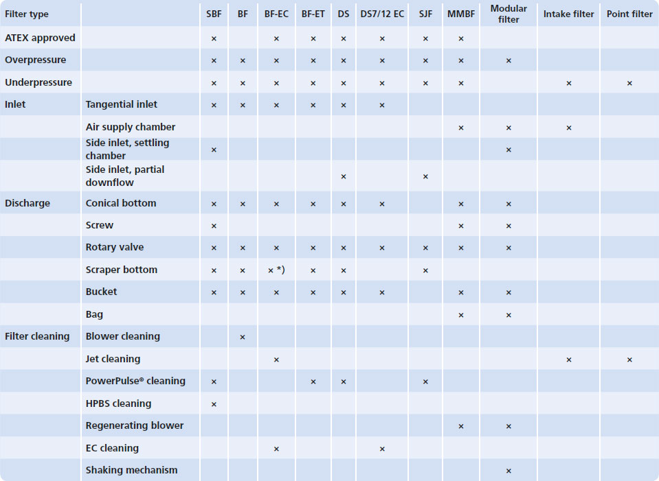
A filter basically consists of an inlet element, the filter, a cleaning system and a discharge element.
Inlet
Depending on type, filters can be supplied with 3 different inlet elements, each with their own characteristics, benefits and areas of use.
- Tangential inlet
- Air supply chamber
- Side inlet, settling chamber
- Side inlet, partial downflow
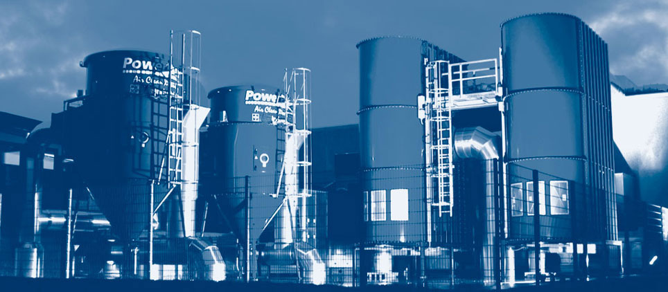
Tangential inlet
Tangential inlet is the most common type. Contaminated air is passed tangentially to the cylindrical filter body. Particles will be thrown outwards towards the outside of the shell by centrifugal force and accelerated, pressing them together. They will then drop to the bottom of the filter.
Air supply chamber
The air supply chamber passes contaminated air into a settling chamber, which in principle is a widening of the conduit diameter - possibly with baffles and guide plates fitted. The velocity of the contaminated air is reduced due to the increase in the volume of the chamber, whereupon the particles drop to the bottom of the filter gravimetrically.
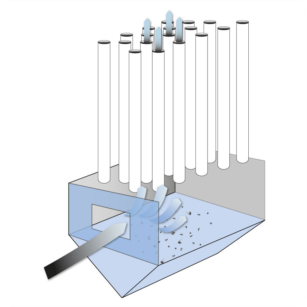
Side inlet settling chamber
The patented Coanda side inlet in some filters uses curved plates to dictate the direction and speed of the air flow. The Coanda inlet reduces pressure loss over the filter by up to 25% in relation to traditional tangential inlet.
The filter inlet is fitted with curved plates which first increase the air flow velocity and then brake and deflect it. The large, accelerated air particles cannot follow the air flow deflection and fall to the bottom of the filter. Consequently, there are fewer particles in the air which passes through the filter bags, and the regulated air flow means even pressure distribution on the filter surface. The result is longer periods between and less energy for filter bag cleaning.
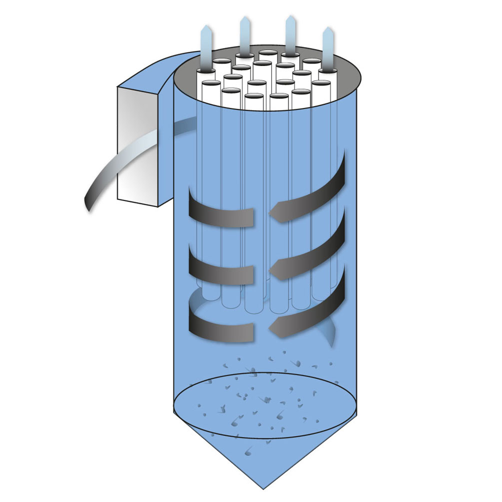
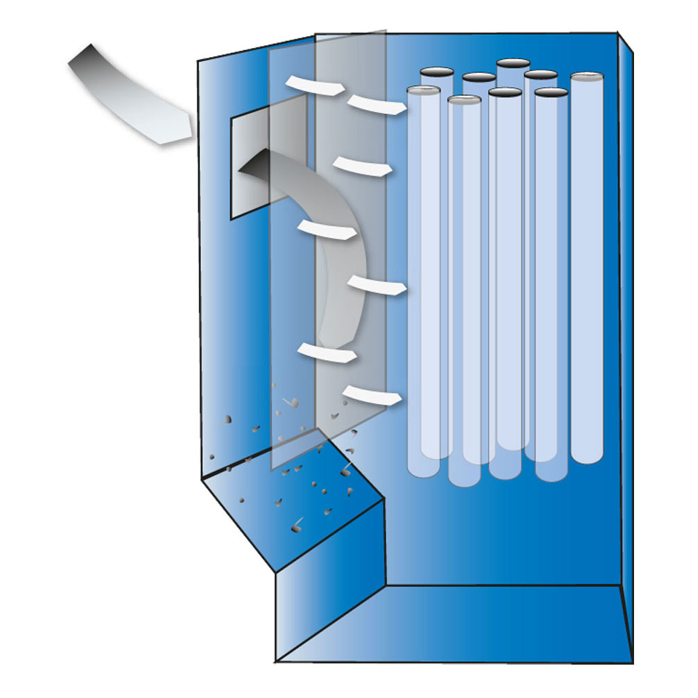
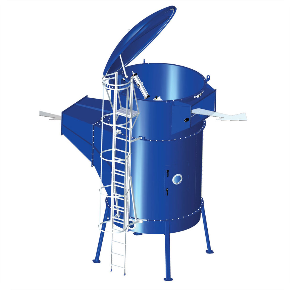
Side inlet, partial downflow
The contaminated air is passed into the filter where it hits a perforated plate. This separates out most of the particles, which bounce off and fall to the filter bottom. Consequently, there are fewer particles in the air which passes through the filter bags, and the regulated air flow means even pressure distribution on the filter surface. The result is longer periods between and less energy for filter bag cleaning.
Side inlet is suitable for material with hard and sharp surfaces.
- More filter inlets and very large filters are possible
- Extremely low pressure loss
- Extended service life
- More effective filtering
- Low noise level
- Extended cleaning intervals
- More flexible planning
- Lower energy consumption
- Lower operating costs
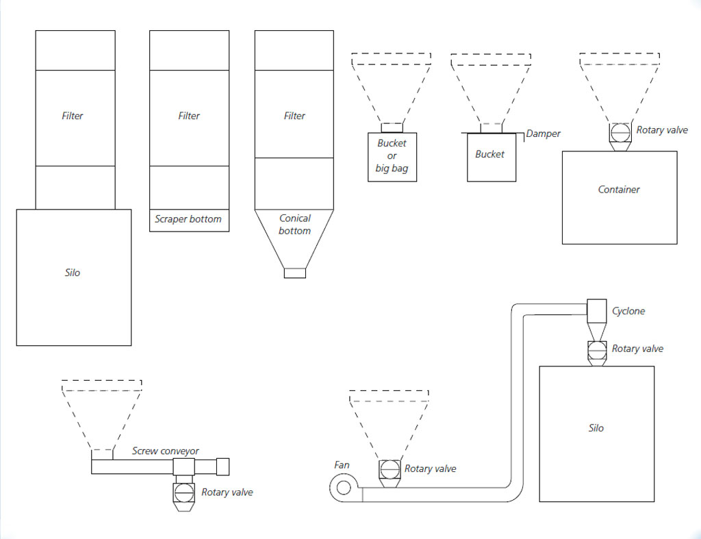
Discharge systems
Filter discharge is adapted and selected according to type and volume of material. See diagram below for discharge systems (according to filter type).Other discharge systems
MMBF and older modular filter types have other discharge systems, such as screw conveyor or chain-mounted conveyors. These systems are described under the respective filter types.
Cleaning systems
Various systems are used to clean the filter units, depending on filter type.- PowerPulse® cleaning
- Blower cleaning
- Jet cleaning
- HPBS cleaning
- EC cleaning
- Regenerating blower
- Shaking mechanism
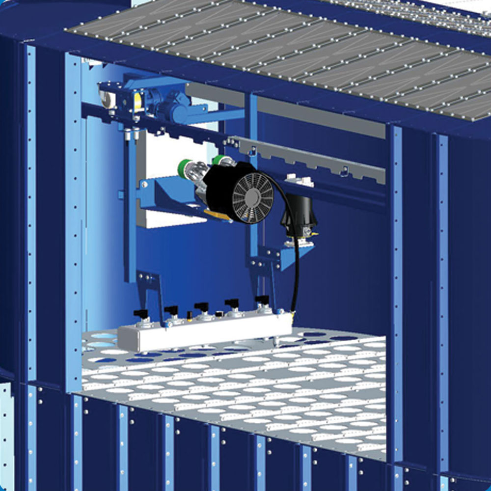
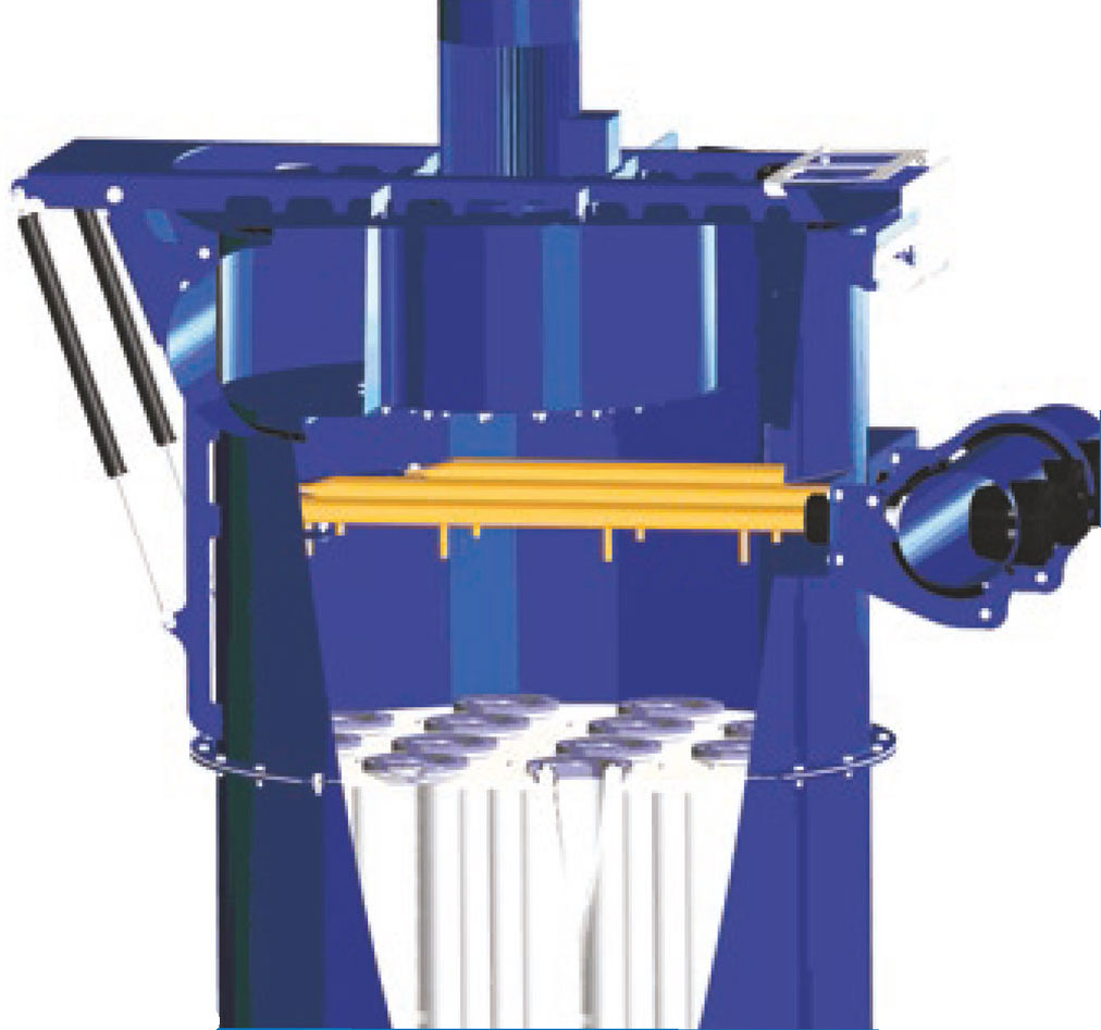
PowerPulse®cleaning
The PowerPulse®cleaning system cleans filter bags using compressed air. The cleaning arm on which the system's jet valves are mounted, moves accurately from bag to bag, dosing precisely and automatically the correct air pressure by measuring air velocity through the filter unit. One filter bag at a time is cleaned.
The PowerPulse® system gives optimum cleaning with lower energy consumption than any other compressed air-based system. PowerPulse® is available for Blower, SuperBlower, DustStorm® and SuperJet filters. These can all be upgraded with PowerPulse®, mounted on the existing filter top.
The PowerPulse® system's low jet pressure of 1.5–3 bar means very low energy consumption, uniform filter cleaning and minimal wear on the filter medium.
The system is available with or without a compressor. The ATEXapproved version is configured for external air pressure. The 2.2 kW maintenance-free dry compressor has a capacity of 350 litres per minute.
PowerPulse® for BF and DS is supplied with ECOTROL® control system. The SuperJet filter is supplied with ECO-PowerPulse®. Both control systems are CPU-based. The communications protocol works with most PCs and PLCs. The ECOTROL® control system monitors all components in the cleaning system, and faults can be displayed on either the main control panel or the control unit.
Blower cleaning
Cleaning is achieved by creating a contraflow air flow in the filter bags. A high pressure blower passes cleaning air through special nozzles to the filter bags.
Cleaning is performed as revolver cleaning of a given number of bags at a time, depending on filter model.
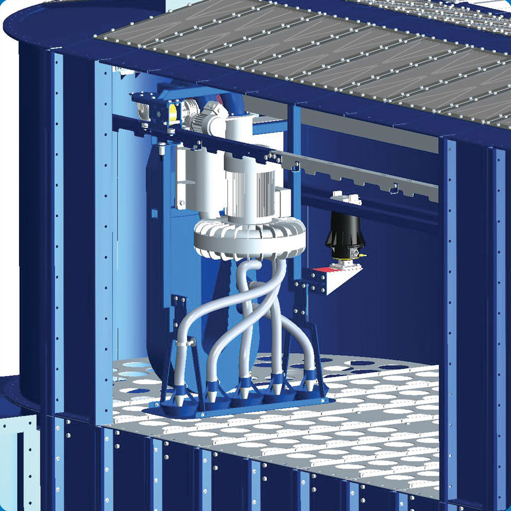
HPBS cleaning
A side channel blower passes cleaning air through special nozzles to the filter bags.
To ensure optimal filter cleaning, the cleaning carriage stops opposite each row of filter bags and cleans according to programmable timer setting. Five filter bags at a time are cleaned. Cleaning can be controlled by a pressure switch which measures pressure difference continuously or using a time relay. The filter only needs to be connected to electricity.
EC cleaning cleans filter units using compressed air. 4 filter elements are cleaned at a time by a single jet valve. The pipes are fitted with speciallydesigned jet nozzles located precisely above each filter element. The jet nozzles provide optimal filter element cleaning.
Benefits:
- Manual setting of pulse and pause times
- Can be controlled either by an external pressure valve or PLC control system
- Total cleaning using a predetermined series of discharges
- One or more cycle "final cleaning" for each shut-down to remove residual dust from the filter. "Final cleaning" starts whenever the fan stops.
The regenerating blower is used for cleaning modular filters. One module at a time is regenerated, as there are partition walls between the modules. The regenerating fan cycle is regulated depending on filter load and dust volume. Cleaning is achieved by reversing the air flow and passing it down through the filter bags, causing dust on the inside of the bags to fall down to the bottom section. The regenerating fan is an axial fan designed to generate high pressure during operation and low flow resistance when idle.
Shaking mechanism
The shaking mechanism only operates during pauses when the filter is not in operation. The mechanism shakes the filter bags, causing dust on the inside of the bags to fall down to the filter bottom.

ATEX explosion relief venting
Dust is often very explosive. The requirements for explosion relief are formulated in the ATEX directive, and are intended to prevent uncontrolled explosive pressure in the event of a dust explosion.
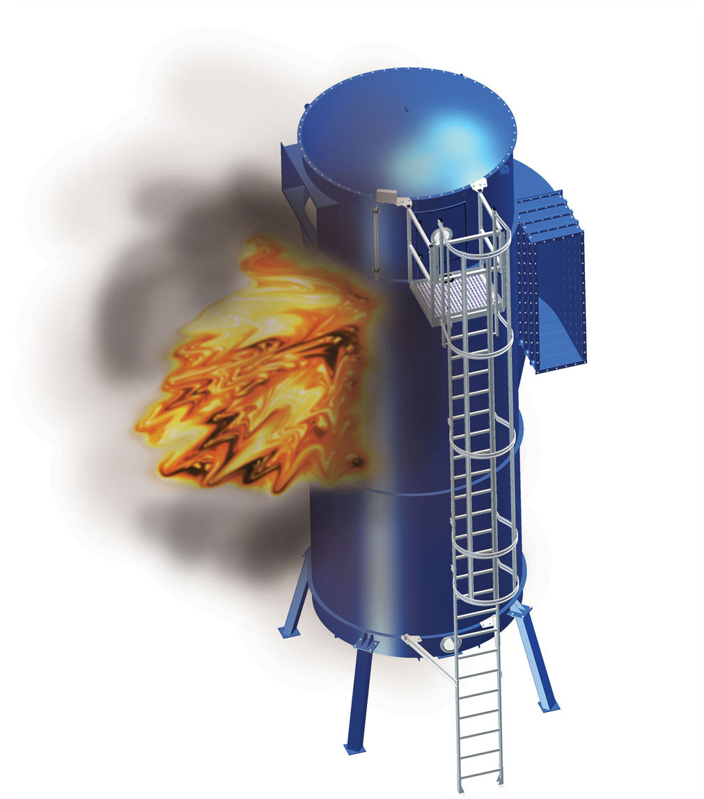
An industrial filter consists of a dust-filled part on the inlet side of the filter bags and a clean air part on the output side. Dust explosions occur in the dust-filled chamber and according to the ATEX directive must either be suppressed or released under control into the surrounding environment. Normal explosion membranes are used for the latter.
According to applicable norms VDI3-673 and VDI2-263, explosion membranes must be located in the dust-filled chamber, unless sufficient explosion relief can be demonstrated. The majority of all industrial filters on the market have the dust-filled chamber at the bottom of the filter. Placing them there means a dust explosion will usually occur as shown in the illustration. By opening the explosion membrane, the explosion pressure is released horizontally. Flames and burning dust particles will be thrown out of the dust-filled chamber and non-ignited dust thrown out can be ignited outside the chamber in a secondary explosion.
The risk of damage to buildings and injury to personnel therefore makes locating the filter in this manner a problem.
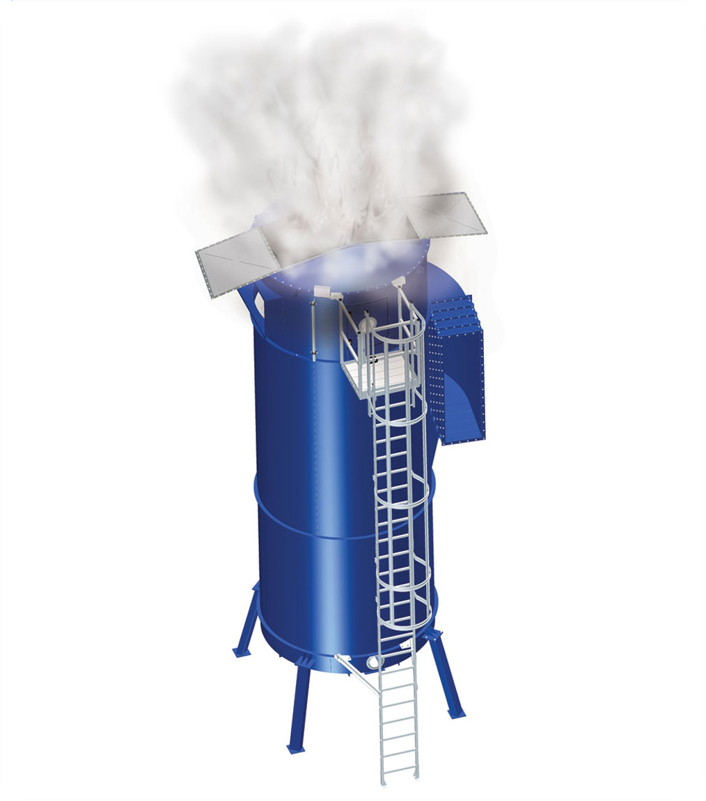
VFV® explosion relief venting
The safety has been increased by venting an explosion vertically into the clean air chamber, as shown in illustration 2. Explosion membranes are placed in the top of the filter. This ensures that explosion dust is kept in the filter bags and only the shock wave has to be vented to the surrounding environment. This eliminates the risk of a secondary explosion, and anyone near the filter at the time will not be exposed to the shock wave.
Optional extras/accessories
Explosion sensors are available for monitoring an installation. The sensor detects if an explosion membrane opens and sends a signal to shut-off other components – e.g. fans.
Explosion sensors can easily be retro-fitted to existing plants.
Explosion conduits are available for filters located outside production facilities. If an explosion occurs, it will be channelled outside via the conduit.
VFV® explosion relief venting has been explosion tested and approved by the German FSA test institute on several of our filters.
Explosion calculation according to VDI 3673, part 1 2002 and European Standard EN 14491:2002 (draft). Calculations performed using WinVent 3.1 E software.
Pressure-resistant up to: Pred, max. = 25 [kPa]
The membranes have an opening pressure of: Pstat = 10 [kPa]
Pressure rise constant set to: Kst = 200 bar × m/s
Calculations apply to wood dust at 20°C.
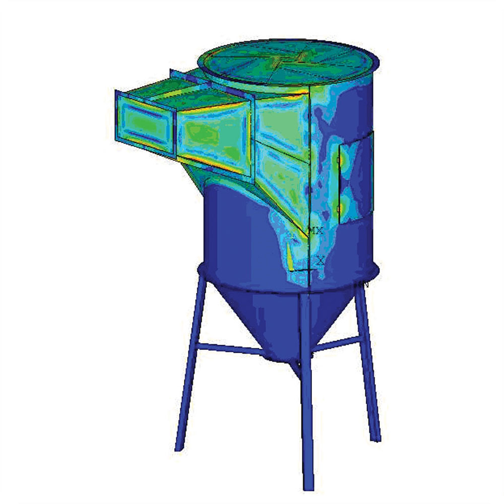
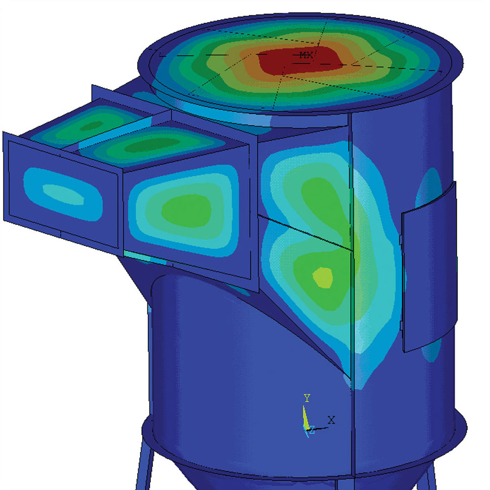
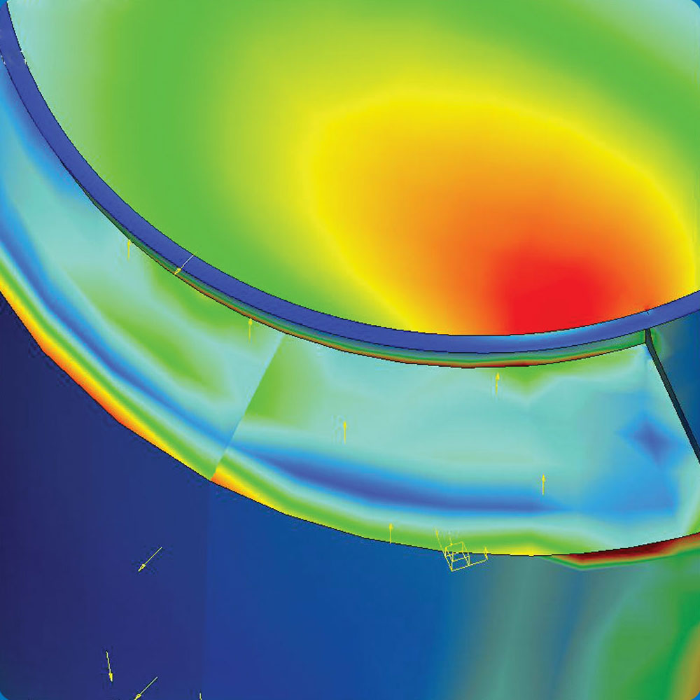
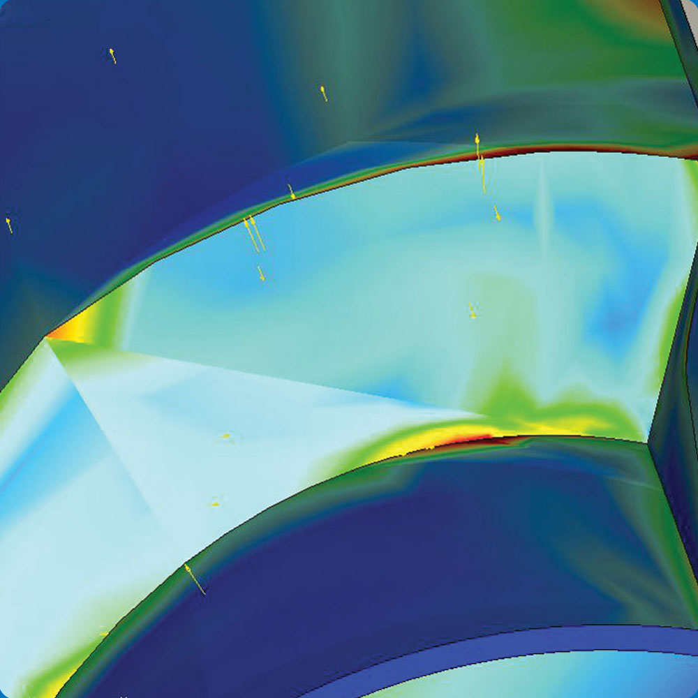
Apart from testing at FSA, we use FEM calculation to determine pressure shock-resistance.
Ladders and gangways
 Ladder and gangway solutions for filters are designed according to ISO/EN/DIN 14122.
ProTechCon has a wide range of different ladders and gangways, so that a solution can be adapted to a given installation using standard parts.
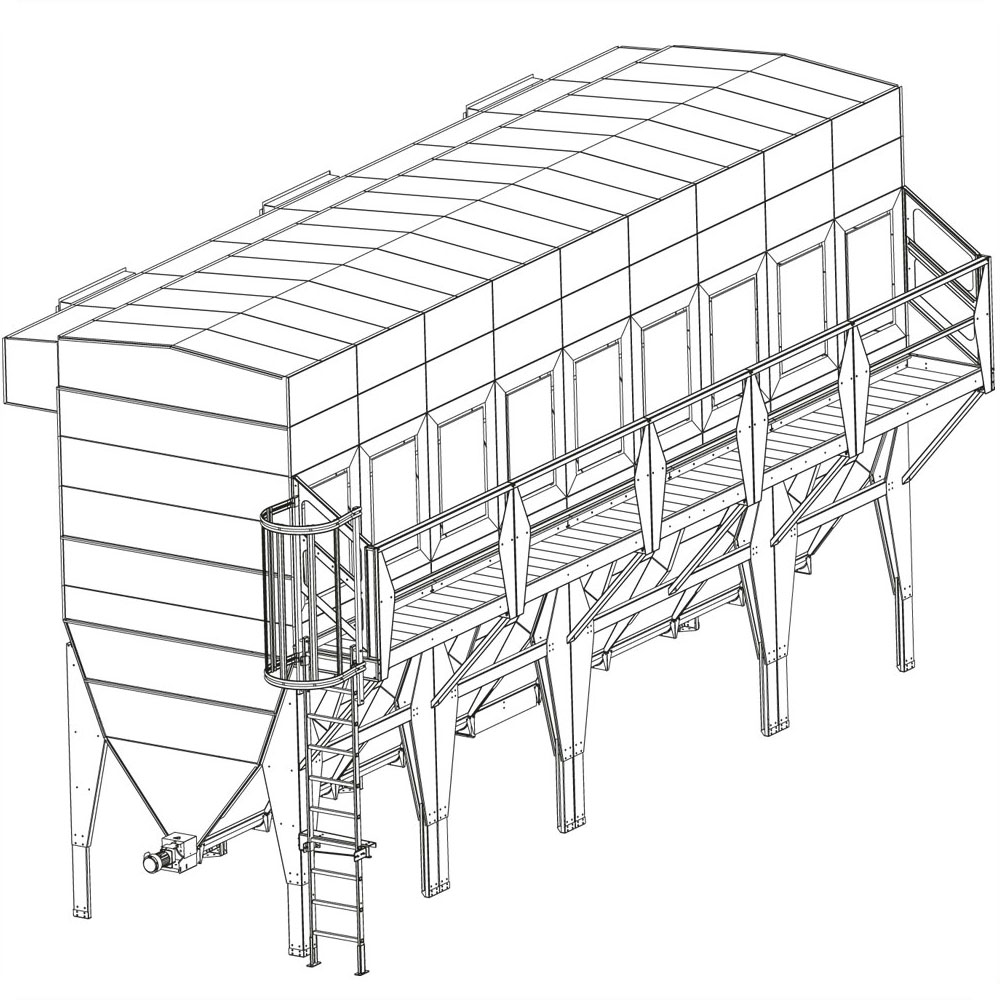
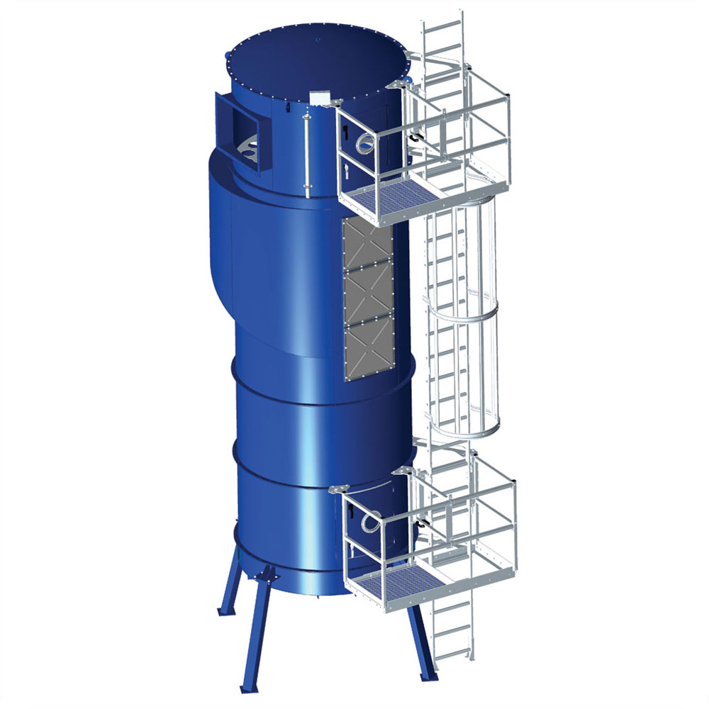
Ladder with gangway SBF
The ladder is mounted close to the filter body with sideways exit onto the gangway. Additional gangways can be attached along the length of the ladder. This provides access to several gangways via a single ladder. Single or double gangways are available. The width of a single gangway corresponds to that of the door section.
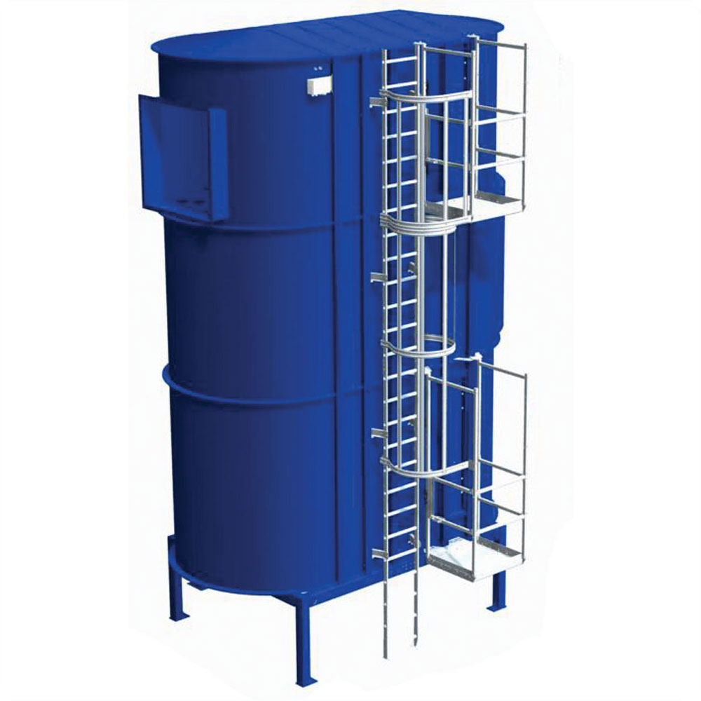
Ladder with gangway, side-mounted SBF
The ladder is at right angles to the filter. Access to the gangway is via the ladder's side rails. Supplied with single and double gangway.
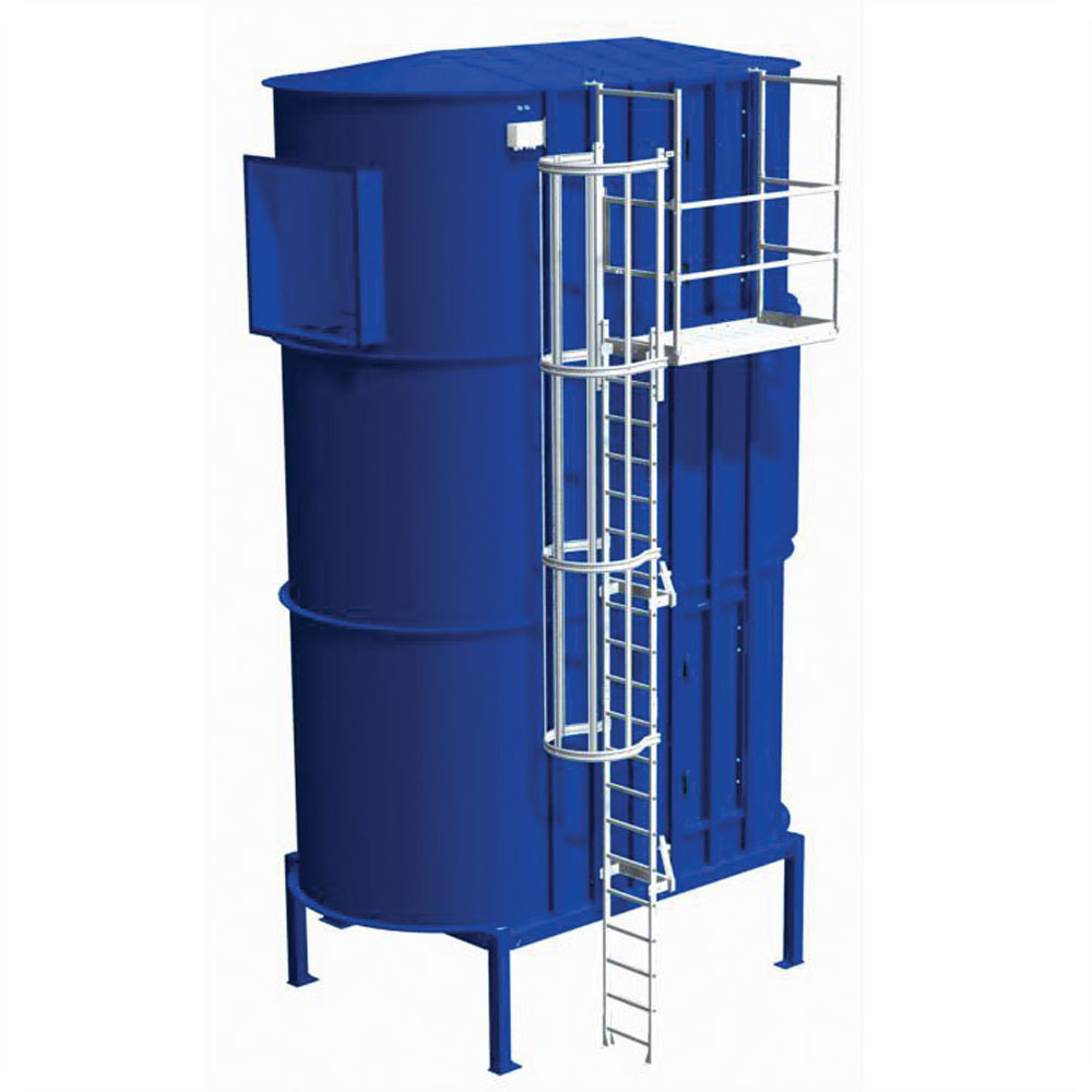
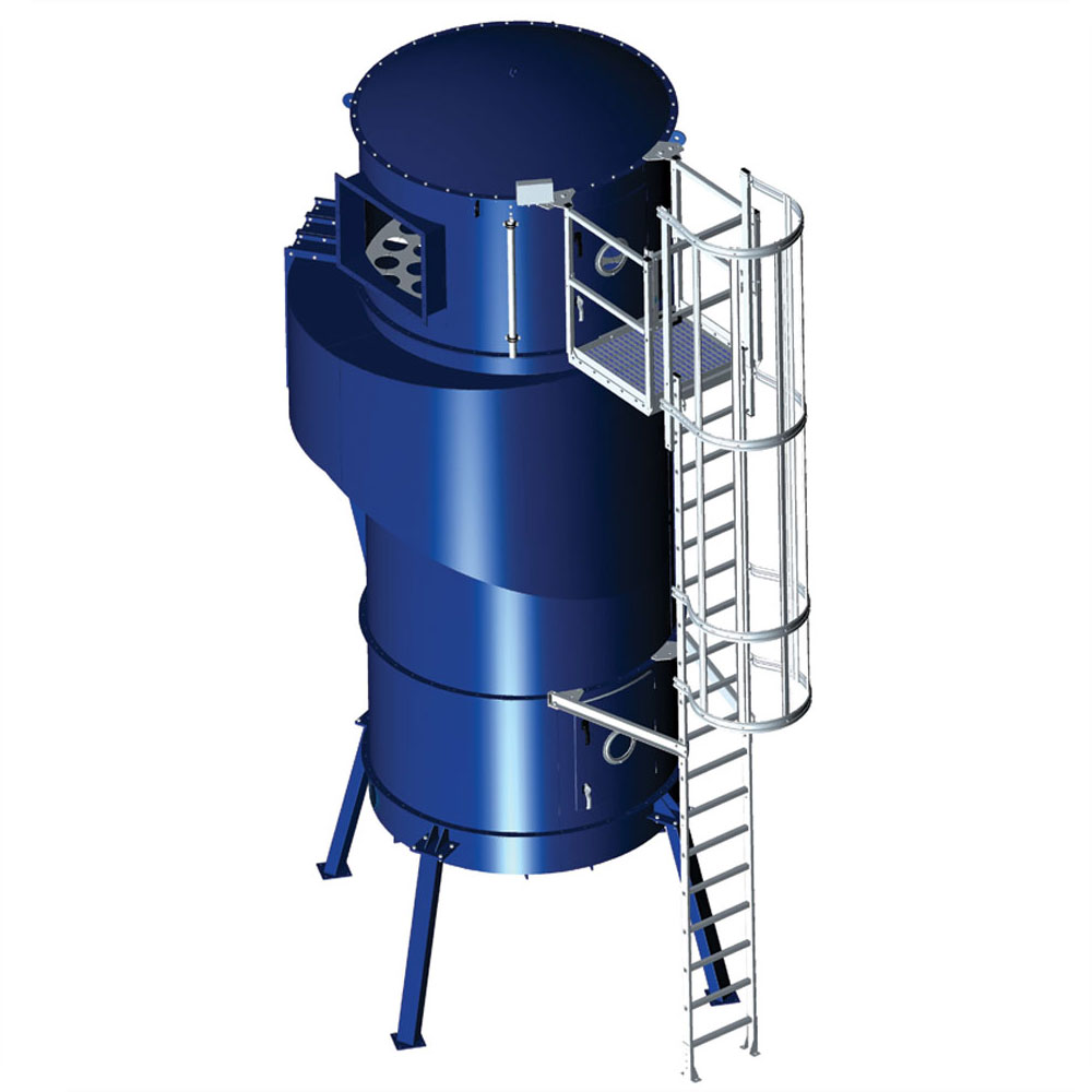
Ladder with gangway, front-mounted on SBF and BFF
The ladder is offset from the filter, making room for pipes run between ladder and filter. Access to the gangway is via the ladder's side rails. Supplied with single gangway only.
Benefits
A modular ladder system means easier adaptation to and expansion of a given installation.
Fewer components simplify installation and overview.
Self-closing hatches on the gangway prevent falls.
-
 Ladder with gangway SBF
 -
 Ladder with gangway, side-mounted SBF
 -
 Ladder with gangway, front-mounted SBF
-
 Ladder with gangway DS
 -
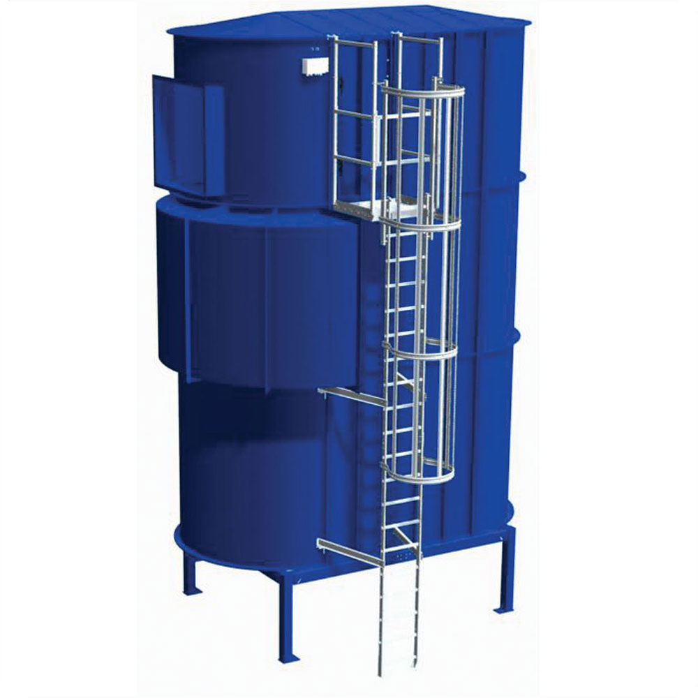
 Ladder with extra double gangway BF
 -
 Ladder with gangway, front-mounted BF
Filters selection
Extraction from industrial premises is usually intended to:
- remove undesirable contaminants such as particles, dust, smells, smoke or gases from process and/or working zones before they spread.
- create balance between the volume flow blown-in and extracted
Extraction in an industrial ventilation scenario is often in the form of point extraction located as close to the source of pollution as possible, and designed for optimal efficiency. Room extraction is also recommended.
Dust separator
Common for many industrial processes is that dust is generated. Pollution sources are multiple, and just about all particle sizes are represented. Air purification can therefore be divided into groups:
- dynamic separators in the form of cyclones and separators
- bag filters, possibly combined with cyclones
- bag filters with integrated tangential inlet
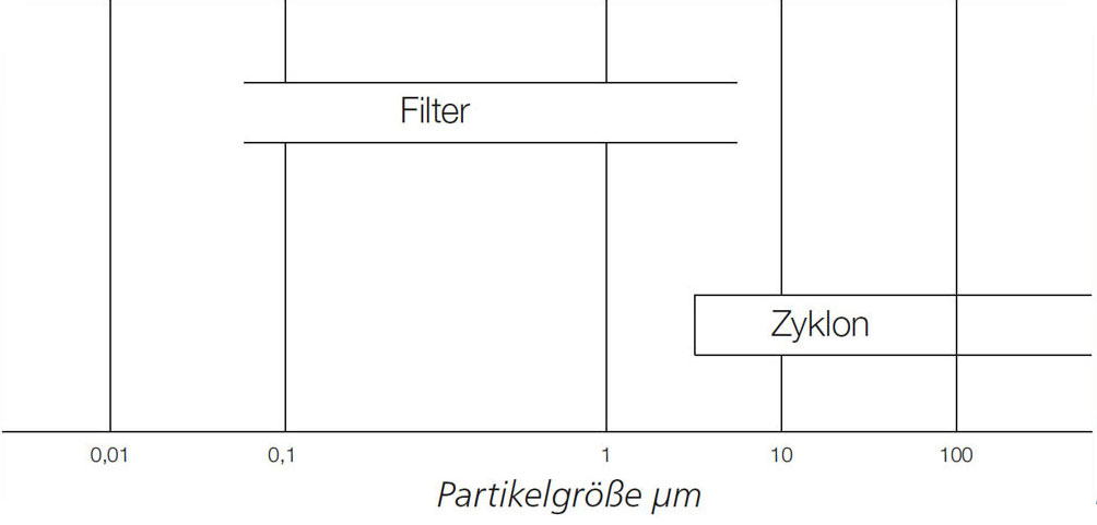
Separation of particles by filtering depends primarily on physical and mechanical effects. Common to all purification methods is that separation efficiency depends on particle size, where the degree of separation rises with rising particle size.
In health terms, particles – of less than 1μm – are by far the most dangerous, as they can reach the respiratory passages via inhalation.
Filters
Filters for material separation are intended to purify exhaust air with strong dust concentrations. Air is purified in the filters by passing through a filter medium, and the degree of separation depends primarily on the density of the medium, particle size and load.
Furthermore, electrostatic forces can help trap and retain particles on the fibres to a certain degree. Filter media are made of synthetic fibre, glass or natural fibres, and come in different thicknesses and degrees of density. We use only approved filter media which are certified.
It is important that air resistance in the filter is kept as low as possible, so that the air flow is not reduced, and energy consumption is kept as low as possible.
Dynamic separators
Dynamic separators are used for the separation of larger particles. As such, they can reduce the amount of dust in the air purified by the filter, ensuring more efficient operation and lower energy consumption. The separator's configuration ensures low pressure loss and material separation with minimal discharge of air.
Cyclones consist of a simple cone-shaped and cylindrical chamber, which reaches a point at the bottom. The contaminated air is passed tangentially in to the top of the cyclone to form a screw-shaped cyclone in the chamber. Centrifugal force throws the particles outwards towards the chamber walls, and they fall to the bottom of the cyclone into a collection box before being passed into a sluice. The purified air is passed through a centrally located discharge at the top of the chamber.
The cyclone principle is mainly suited to the separation of coarse particles. The degree of separation is typically 70-80% for particles around 5 mm in diameter. The degree of separation in a cyclone increases with rising air velocity inlet and narrower diameter.
Cyclones can also be used as separators in combination with another form of air purification.
Mechanical separation of particles takes place in a separator. Dust-filled air is passed into a chamber, where a rotor runs against a perforated plate. The rotor directs larger particles (over 3 mm) towards a discharge in the bottom of the chamber, whilst the air and smaller particles diffuse through the perforated plate and on to a filter.
Dynamic separation means that the separator can be more compact than a settling chamber.
Filtration degrees
The filters are intended for the purification of exhaust air with heavy dust concentrations, and can be in the form of cartridge or bag filters. Air is purified in the filters by passing through a textile filter medium, and the degree of separation depends primarily on the density of the medium. Separation efficiency is up to 99.98%.