")
Fan Systems
General
Resistance occurs in all forms of air transport due to friction which means that overall pressure is reduced in the flow direction. To effect and maintain air transport, pressure has to be increased at some stage to compensate for pressure loss. This is usually achieved in fan systems using radial and axial fans designed to boost air flow in the direction of the outlet.
Definitions:
Static pressure: ps
Dynamic pressure: pd
Total pressure: pt
Static pressure is designated positive or negative depending on whether there is over or under pressure in the duct. On the other hand, dynamic pressure is always positive and depends on the speed of the air in the duct.
Total pressure must always be equal to the sum of the static and dynamic pressure at the measurement point, which can be expressed as: pt = ps + pd
Volume flow
A fan’s effect is always based on actual volume flow through the inlet. If the volume flow is indicated at a temperature different to that at the fan in a given operating situation, it must be corrected.
Temperatures
The graphs indicate 20°C. Fans can be used for temperatures up to 60°C without physical modification.
At temperatures other than 20°C, the air density is changed. This means it may be necessary to adjust the min-1. At temperatures over 20°C the fan will generally be giving reduced effect in relation to the rise in temperature.
For high temperatures, the following should be taken into consideration:
bearings and lubricant - whether the fan should be fitted with cooling wings – whether the motor should be supplied with extra cooling (particularly important for frequency regulation). For temperatures in excess of 60°C, extra cooling is required.
Fan types
Motors and fans are usually supplied as a unit. JKF has designed its fans for optimal performance, and it is vital to select the right one for any given task. The speed at which the fan is to run can be seen from the graph for that fan. The power input required depends on resistance in the system.
There are many types of fan impeller, each of which is designed for a given task:
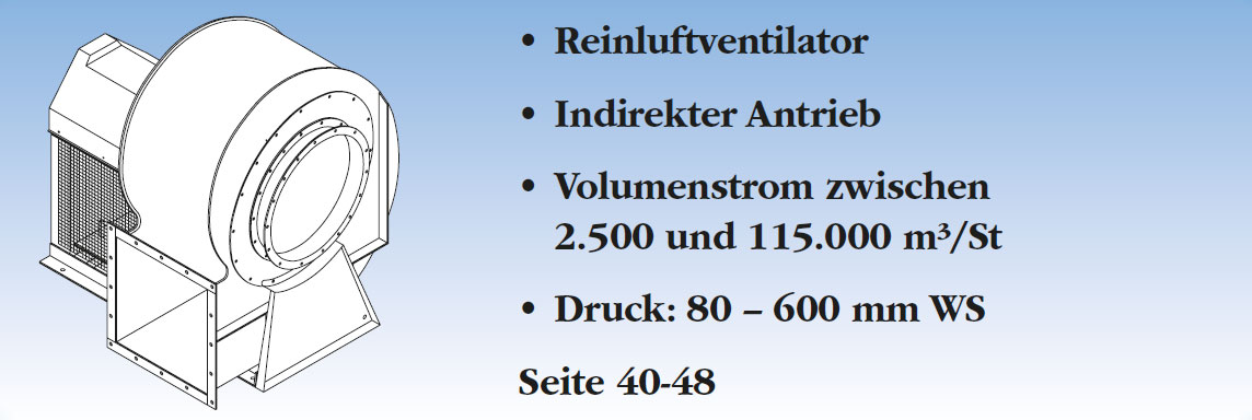
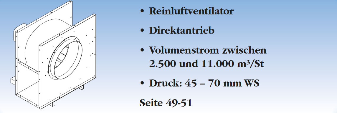
- Radial fan with P-impeller
- Radial fan with T-impeller
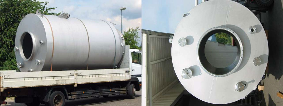
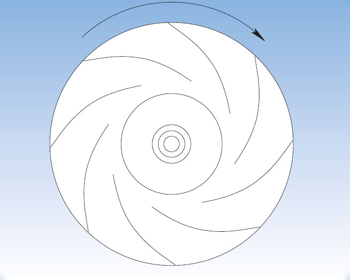
Radial fan with P-impeller
Has flat backward-inclined blades and is designed for clean air transport.
This type has the following properties:
- High efficiency
- Robust construction
- Only small variations in volume flow if resistance fluctuates.
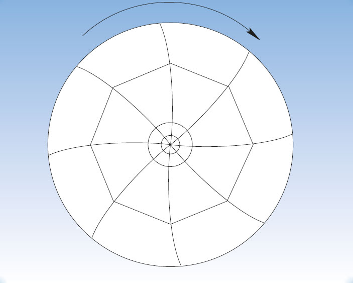
Radial fan with T-impeller
Has backward-inclined blades and is designed for transport of a range of materials. This type has the following properties:
- Medium and high-pressure versions
- Robust construction
- High degree of self-cleaning
- Can handle large material volumes
- Special version available for transport of plastic and paper
All fans are ATEX-certified in accordance with Directive 94/9 EF.
Fan selection
Useful effect
Theoretical pressure increase is never achieved in practice, as all fans work with several unavoidable types of loss, including:
- Friction loss in housing and impeller
- Thrust loss at blade inlet
- Leakage between housing and impeller
- Loss due to impeller friction
- Loss in motor, belts and bearings
PTC states the total useful effect.
The useful effect for a given operating point indicates the relationship between the utilisation effect (air effect) and the power input (shaft effect). The utilisation effect is the product of volume flow and total pressure increase.
The useful effect of the fan can be expressed as follows:
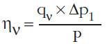
and its effect consumption as:
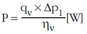
where
P = shaft effect [W] of the fan
qv = volume flow [m3/s]
Δp1 = total pressure increase [Pa]
ην = useful effect of the fan [decimal fraction]
Any loss from the belt drive and motor have to be added, so that total effect consumption can be expressed as:
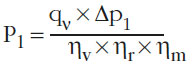
where
ηv = Ventilatornutzleistung
ηr = Keilriemennutzleistung
ηm = Motornutzleistung
Fan diagram
For description of fans for specific solutions, the following parameters are required:
- Volume flow
- Pressure increase
- Effect consumption
- min-¹
- Useful effect
- Noise intrusion
Fan graphs are based on a density of 1.2 kg/m³ equivalent to air density at 20°C and barometric pressure of 101.3 kPa.
Capacity regulation of fans
All fan systems of any size can be fitted with capacity regulation to match volume flow to the usage patterns of the plant. Depending on operating requirements, fan performance can be regulated in several ways:
- Pole-switching between two fixed speed regulator values (2-speed motor)
- Twist throttle on fan inlet side
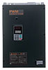
- min-¹ regulation using a frequency transformer
- A combination of the above
Using a frequency transformer maintains the fan useful effect almost unchanged across the entire regulation range and avoids noise being created during regulation.
Accessories
- wist throttle is available as a component
- 60 Hz impeller for transport fan
The impeller has to b e modified for 60 Hz direct driven transport fans.
Belt-driven fans are adjusted via the pulleys.
The SKF bearing housings on the fans are types SNL…TA, with V- gasket TSN…A.
Surface treatment
PTC-painted filters fulfil corrosion class C3, cf. ISO 12944. JKF has the latest powder-coating equipment – a 3 zone, high-tech computer-controlled and fully automatic installation which ensures high and uniform quality for all painted items, for painting small items (B1,0×H2,0×D0,5 m). Powder is applied by robot with coat thicknesses of 100 - 120 my.
A powder coating plant for larger items (B2,5×H2,5×D4,0 m) is used with integrated sandblasting facility. Powder application is manual.
Prior to the paint application, the items is sandblasted to SA2,5 using steel balls. The items are blown thoroughly clean and their surfaces sanded to ensure maximum adhesion.
Powder coating has a number of benefits:
- high quality, impact and scratch-resistant surface
- high material usage – no evaporation
- Less impact on the environment, no solvents.
If a higher corrosion class is required, please specify when ordering. JKF can supply products which fulfil up to corrosion class C4 cf. ISO 12944. All painted standard products are blue RAL 5010. Can be delivered in other colors against an additional charge. The impeller are supplied untreated due to the balancing. The standard version of the electric motor is black. Can be delivered in other colors against an additional charge and an extended time of delivery.
Test
All fans are tested for function and vibration.
When ordering, JKF requires the following information:
Fan type – air volume – air temperature - pressure – material transport/ nature – installation conditions – noise levels – effect consumption - motor – motor integrity class – operating time - surface treatment, zone placing (ATEX) – and any other requirements.